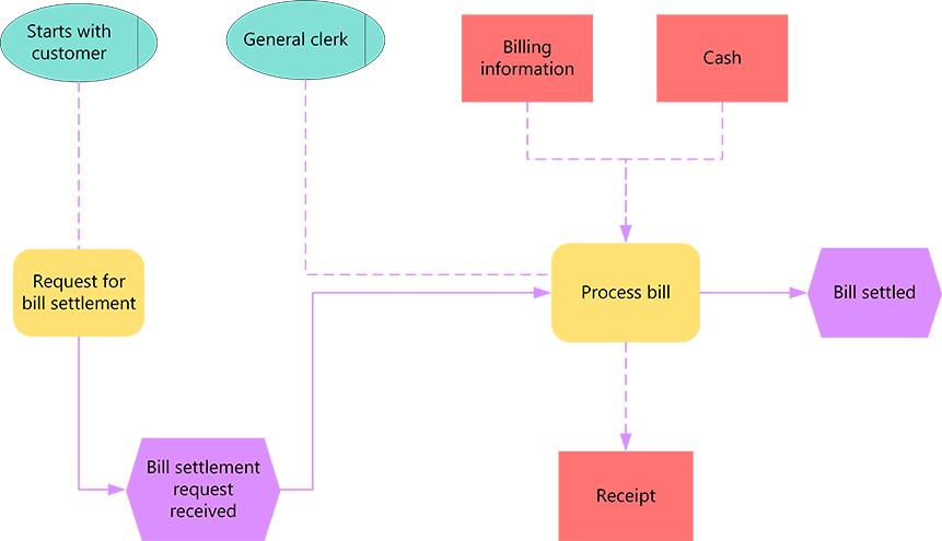
Event-driven Process Chain (EPC) diagrams illustrate business process work flows and are an important component of the SAP R/3 modeling concepts for business engineering. EPC diagrams use graphical symbols to show the control-flow structure of a business process as a chain of events and functions.
The Event Driven Process Chain (EPC) is one popular modelling notation and the Business Process Modelling Notation (BPMN) is another. People are sometimes confused which of the two provides a better fit or utility for visualising and communicating business processes.

The EPC is most often used to model higher-level business processes. However, there are cases where these have been used for executable modelling. BPMN would be most often better for lower-level process modelling.
The Event Driven Process Chain (EPC) is one popular modelling notation and the Business Process Modelling Notation (BPMN) is another. People are sometimes confused which of the two provides a better fit or utility for visualising and communicating business processes. EPCs do not support semi-structured processes, whereas ad-hoc sub-processes can be implemented in BPMN. EPC cannot be easily used to describe executable processes.
Use the EPC Diagram template or EPC diagram shapes in Visio to create a high-level, visual model of your business process.
The building blocks used in EPC diagrams are:
-
Functions, which are the basic building blocks of the diagram. Each function corresponds to an executed activity.
-
Events, which occur before or after a function is executed or both. Functions are linked by events.
-
Connectors, which associate activities and events. There are three types of connectors: AND, OR, and exclusive OR (XOR).
After it is completed, you can use the EPC diagram as a reference for modeling the SAP R/3 system.
Create an EPC diagram
- Open Visio.
- Create a new diagram from the EPC diagram template, which can be found in the Business category.
- From EPC Diagram Shapes, drag the shapes that you want to represent your business process onto the drawing page.
- Connect the shapes:
- Drag a shape from a stencil onto the drawing page and position it near another shape.
- While still holding down the mouse button, move the pointer over one of the blue triangles. The triangle turns dark blue.
- Release the mouse button. The shape is placed on the drawing page, and a connector is added and glued to both shapes.
Tip: To reverse the direction of the arrow on a connector, you can reverse the ends of a connector by clicking the Reverse Ends command. In order to be able to do that, you have to first add the Reverse Ends command to the ribbon. For more information, see Reverse the direction of a connector arrow.
Notes:
- To add text to a shape, select it, and then type. When you finish typing, click outside the text block.
- To edit text, double-click the shape, place the cursor where you want to change the text, and then edit as necessary.
- To hyperlink a shape to supporting or explanatory documents, right-click the shape and select Hyperlink.
- To align multiple shapes vertically or horizontally, select the shapes you want to align, and then on the Home tab, click Align and select an option