DFD Diagram Notations
Now we'd like to briefly introduce to you a few diagram notations which you'll see in the tutorial below.
External Entity
An external entity can represent a human, system or subsystem. It is where certain data comes from or goes to. It is external to the system we study, in terms of the business process. For this reason, people used to draw external entities on the edge of a diagram.
.png)
Process
A process is a business activity or function where the manipulation and transformation of data take place. A process can be decomposed to a finer level of details, for representing how data is being processed within the process..png)
Data Store
A data store represents the storage of persistent data required and/or produced by the process. Here are some examples of data stores: membership forms, database tables, etc.![]()
Data Flow
A data flow represents the flow of information, with its direction represented by an arrowhead that shows at the end(s) of flow connector..png)
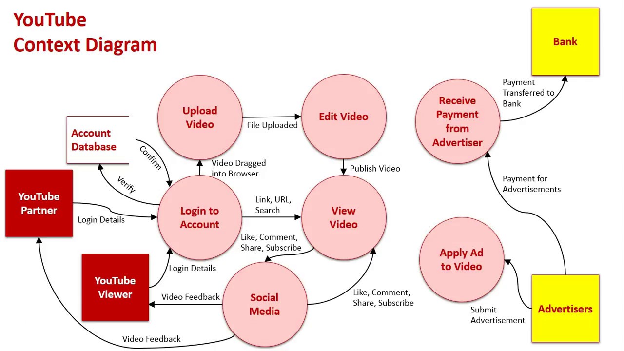
DFD Level 0
DFD Level 0 is also called a Context Diagram, shows a data system as a whole and emphasizes the way it interacts with external entities.. It's a basic overview of the whole system or process being analyzed or modeled.

Usually, DFD Level-0 is created with Data Dictionary during the project initial stage.
A Data Dictionary, also called a Data Definition Matrix, provides detailed information about the business data, such as standard definitions of data elements, their meanings, and allowable values. While a conceptual or logical Entity Relationship Diagram will focus on the high-level business concepts, a Data Dictionary will provide more detail about each attribute of a business concept.
Essentially, a data dictionary provides a tool that enables you to communicate business stakeholder requirements in such a way that your technical team can more easily design a relational database or data structure to meet those requirements.
Learn more: https://www.bridging-the-gap.com/data-dictionary

DFD Level 1
A level 1 DFD notates each of the main sub-processes that together form the complete system. We can think of a level 1 DFD as an “exploded view” of the context diagram.

DFD Level 2
A level 2 data flow diagram (DFD) offers a more detailed look at the processes that make up an information system than a level 1 DFD does. It can be used to plan or record the specific makeup of a system.

How do you create a level 2 data flow diagram?
-
Make the process box on the level 1 diagram the system boundary on the level 2 diagram that decomposes it. This level 2 diagram must balance with its “parent” process box — the data-flows to and from the process on the level 1 diagram will all become data-flows across the system boundary on the level 2 diagram. The sources and recipients of data-flows across the level 2 system boundary are drawn outside the boundary and labelled exactly as they are on the level 1 diagram. Note that these sources and recipients may be data stores as well external entities or other processes — this is because a data store in a level 1 diagram will be outside the boundary of a level 2 process that sends or receives data-flows to/from the data store.
-
Identify the processes inside the level 2 system boundary and draw these processes and their data-flows. Remember, each data-flow into and out of the level 2 system boundary should be to/from a process. Using the results of the more detailed investigation, filter out and draw the processes at the lower level that send and receive information both across and within the level 2 system boundary. Use the level numbering system to number sub-processes so that, for example, process 4 on the level 1 diagram is decomposed to sub-processes 4.1, 4.2, 4.3 … on the level 2 diagram.
-
Identify any data stores that exist entirely within the level 2 boundary, and draw these data stores.
-
Identify data-flows between the processes and data stores that are entirely within the level 2 system boundary. Remember, every data store inside this boundary should have at least one input and one output date flow.
-
Check the diagram. Ensure that the level 2 data-flow diagram does not violate the rules for data-flow diagram constructs.
DFD Level 3
This could continue to evolve to become a level 3 diagram when further analysis is required, but anything beyond level 3 is not very common.

Advantages of data flow diagram:
- It aids in describing the boundaries of the system.
- It is beneficial for communicating existing system knowledge to the users.
- A straightforward graphical technique which is easy to recognise.
- DFDs can provide a detailed representation of system components.
- It is used as the part of system documentation file.
- DFDs are easier to understand by technical and nontechnical audiences
- It supports the logic behind the data flow within the system.
Disadvantages of data flow diagram:
- It make the programmers little confusing concerning the system.
- The biggest drawback of the DFD is that it simply takes a long time to create, so long that the analyst may not receive support from management to complete it.
- Physical considerations are left out.